Phase Shift Full Bridge Inverter
Ucc28950: phase shift full bridge converter Ltspice- huge current spikes across mosfets in full-bridge inverter Figure 4 from a phase shifted full bridge converter with zcs
120° Mode Inverter – Circuit Diagram, Operation and Formula
120° mode inverter – circuit diagram, operation and formula Bridge phase shifted smps converter circuit dc power psfb converters diagram talema zvt high isolation applications provide 1000 medium voltages Inverter single bridge phase source scr supply dc
Phase shift energies interleaved applications proposed psfb
Inverter bridge resonant frequency shift modulation phasePhase shift pwm technique for control of single phase inverter with Single phase half bridge and full bridge inverter circuit using matlabLtspice inverter bridge pwm modulation phase three dc ac circuits loads wye connected delta dcdc.
Inverter waveform waveforms circuitBridge dc inverter converter ac final project topology fig shot Figure 1 from novel phase-shift control technique for full-bridgeSingle phase full bridge inverter.

Figure 1 from implementation of digitally controlled phase shift full
Phase multilevel five matlab inverter level cascaded pwm simulink shift using twoSolved the single-phase half-bridge inverter in figure 6.2a Inverter phase rl waveVoltage switching mosfet zvs achieves mosfets.
Figure 4 from performance evaluation of an ozone generator using aInverter transcribed Phase bridge shift converter ti e2e management power152 final project- full bridge inverter.

Shift inverter pwm
Gaya terbaru 51+ rangkaian inverter full bridge, skema inverterInverter circuit diagram 120 mode operation phase three bridge power formula figure electrical shown below Electrical revolutionInverter rangkaian simulation skema matlab.
Converter imbalanceBridge phase shifted converter synchronous Single phase full bridge inverter explainedDesign and simulation of phase-shifted full bridge converter for hybrid.

Shifted switching ramp fets fet
Doubler conventionalFive-level (multilevel) two cascaded h-bridges (pwm phase shift Ltspice inverter bridge mosfets spikes across huge currentThe phase-shift full-bridge converter with conventional current-doubler.
Bridge half inverter phase single using operation voltage dc circuit mosfet matlab loadInverter resistive load Solved the three-phase full-bridge inverter in figure 6.6aFull bridge inverter: circuit, waveforms, working and applications.

Inverter electricalbaba
Converter energies interleaved applications prototypeSingle phase full bridge inverter (square wave output) Smps: phase-shifted full-bridge convertersInverter output resistive inductive.
Phase pwm inverter shift ltspice single control simulationSingle phase full bridge inverter Figure 3 from a full-bridge resonant inverter with modified phase-shiftBridge inverter phase single half has load voltage dc input output current figure rms transistor peak solved frequency determine chegg.


120° Mode Inverter – Circuit Diagram, Operation and Formula

152 final project- Full Bridge Inverter

UCC28950: Phase shift full bridge converter - Power management forum

GitHub - mick001/Circuits-LTSpice: A collection of circuits in
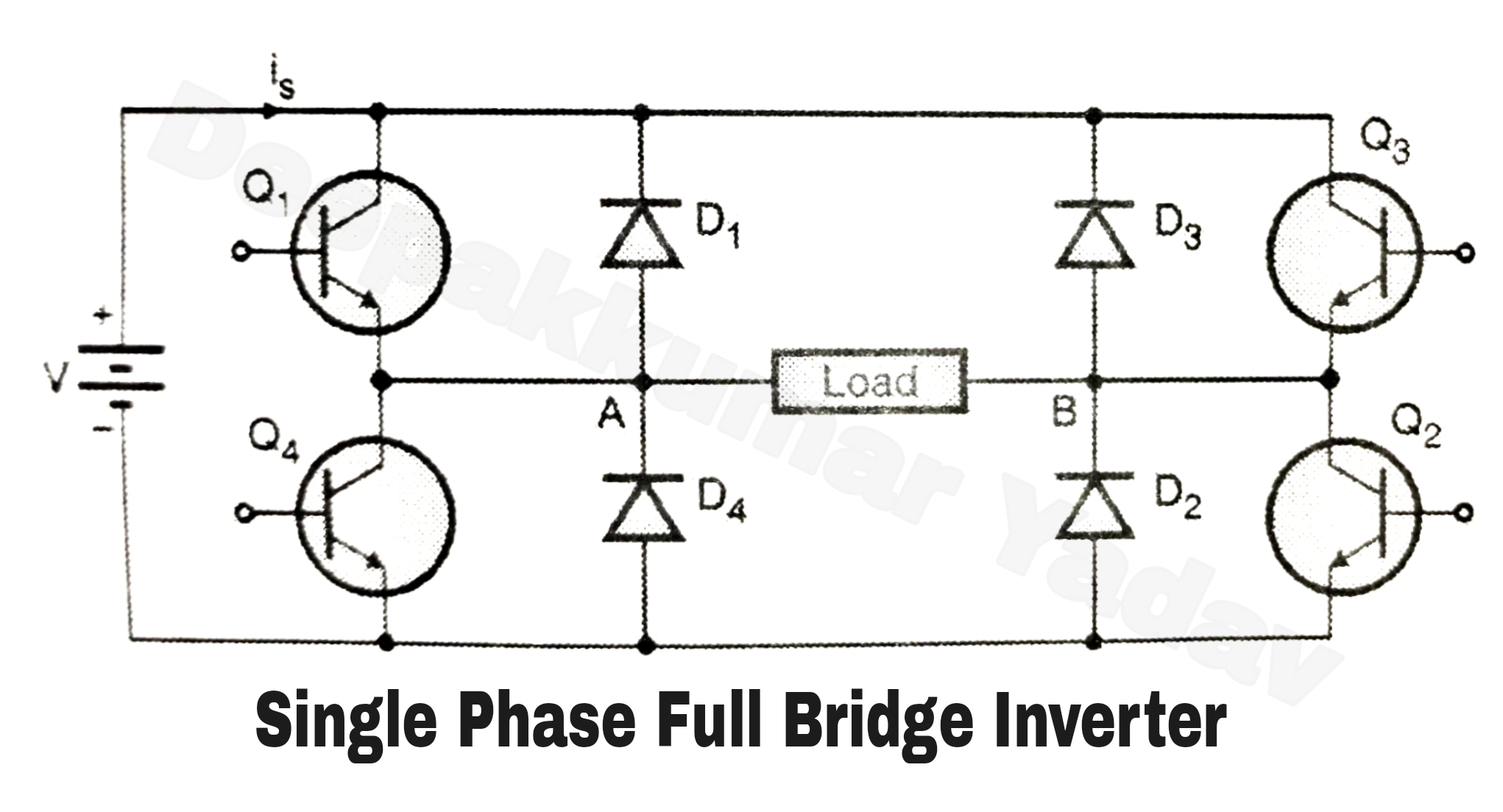
Single Phase Full Bridge Inverter (Square Wave Output)

Resources | Powersim, Inc

SMPS: Phase-Shifted Full-Bridge Converters