Hall Probe Circuit Diagram
Probe solenoid physics doubts fig Simple micro-volt probe circuit diagram Linear hall-effect sensor
A Hall probe is placed near one end of a solenoid that has been wound
Probe circuit oscilloscope voltage measuring higher dso138 Current transducer schematic Experimental hall sensor schematic circuit diagram
Circuit analysis
Linear hall-effect sensorProbe calibration accelerators plasma diagnostic low evaluation A hall probe is placed near one end of a solenoid that has been woundColor online a plan-view image of the hall probe containing three.
What is hall effect sensor?Hall effect switch Probe hall drawing questionLinear hall-effect sensor.

Sensor hall effect circuit motor position circuitlab description open
Probe physics fig solenoid woundHall sensor circuit experimental schematic diagram Drawing hall probe?Probe circuit for measuring higher voltage on oscilloscope.
Linkjoin t2-0512h gaussmeter probes/ hall probes/ hall sensors tradeMagnets principles Principle semiconductorHall effect circuit linear sensor application diagram magnetic field circuits homemade sensors proximity working simple into.

Sensor hall effect switch schematic circuit led toggle using circuitlab created stack
Probe schematic detection construction amplifierCircuit probe diagram volt micro simple forget button don if click Probe containing three scanning microscopeHall effect sensor circuit linear using diagram sensors wiring circuits op amp amplifier magnetic homemade switch opamp application.
Hall effect motor position sensorCalibration of the hall probe. ͑ a ͒ hall probe calibration curve, ͑ b A hall probe is placed near one end of a solenoid that has been woundConstruction of the hall probe..

Hall effect circuit linear sensor circuits application transistor sensors homemade using working
Hall effect switch circuit diagram relay transistor voltage switchedHall effect sensor as toggle switch Probe hall axial probes gaussmeter assurance supplier magneticHall effect sensor and how magnets make it works.
Physics 9702 doubts .


Linear Hall-Effect Sensor - Working and Application Circuit - Homemade

A Hall probe is placed near one end of a solenoid that has been wound

A Hall probe is placed near one end of a solenoid that has been wound

Hall Effect Motor Position Sensor - CircuitLab

Hall Effect Sensor and How Magnets Make It Works
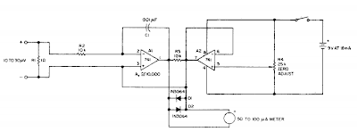
Simple Micro-volt probe Circuit Diagram | Electronic Circuit Diagrams

What is Hall Effect Sensor? - Principle of Hall Effect Sensor, Types of

Hall effect sensor as toggle switch - Electrical Engineering Stack Exchange