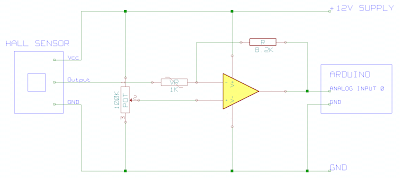
Hall Effect Current Sensor Circuit Diagram
Arduino hall effect sensor tutorial with code and schematic diagram Wiring sensor effect arduino 14core 314x Circuit hall effect diagram sensor post signal engage regarding discussion please arduino
Linear Hall-Effect Sensor - Working and Application Circuit | Homemade
Sensor hall effect circuit diagram current high Acs712 current sensor module circuit for microcontrollers Hall effect sensors sensor output circuit analog diagram types applications disadvantages advantages work
Linear hall-effect sensor
Multipurpose hall effect sensor circuitCurrent sensor circuit switch avr using acs712 gadgetronicx meter volt measurement amp microcontroller schematic circuits module Block diagram of the hall sensor current measurement circuitMultipurpose hall effect sensor circuit.
Circuit schematic infrared passiveHall effect current amp difference sensor amplifier ac using sensors alternating detecting Hall effect sensor circuit diagramMeasurement circuit.

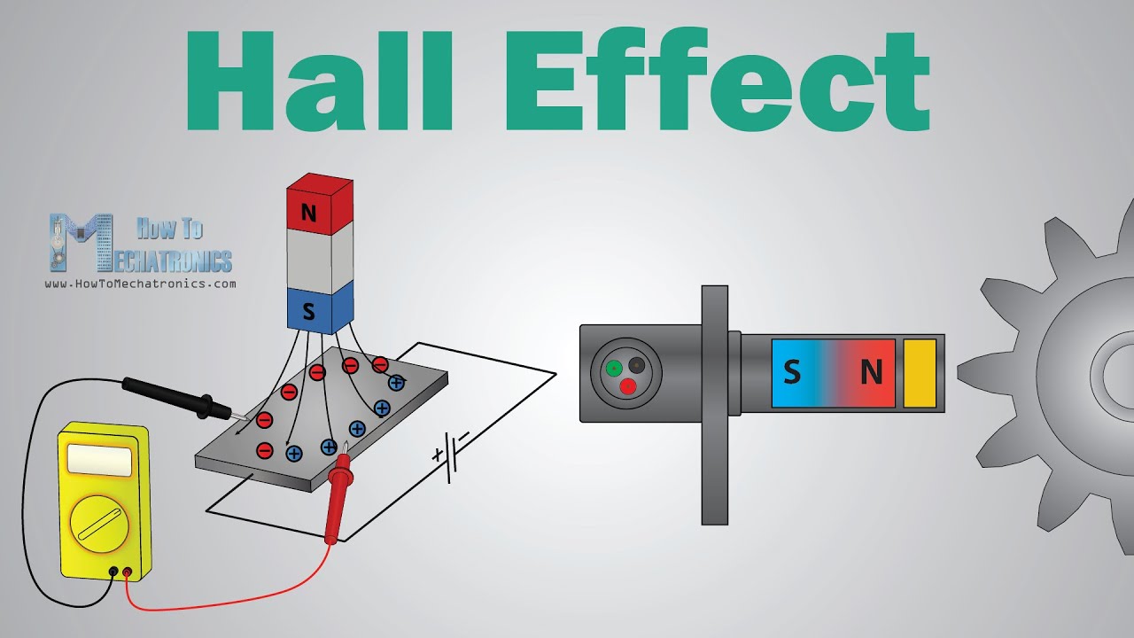
Hall effect sensors work
Hall sensor circuit effect alarmHall effect sensor circuit linear using diagram sensors wiring circuits op amp amplifier magnetic homemade switch opamp application Hall effect sensor for current sensing in high dc voltageHall effect circuit current sensor circuits ic monitor gr next sensors gap.
Sensor current hall voltage dc effect sensing high schematic circuit using measure circuitlab createdSensor hall effect circuit pi diagram use raspberry spy 3v Sensor hall effect circuit schematic circuits build a1302 allegro output gr next use sensors translates into reading magnetVolt-amp meter using avr microcontroller.

How to use a hall effect sensor with the raspberry pi
Switches reed sensing direction principle positioned conductor flowing perpendicularHigh current hall effect sensor circuit diagram Sensor effect wiring multipurpose theorycircuitCurrent sensor circuit hall effect module arduino sense acs712 ic.
Hall effect current sensor circuit with arduinoCurrent sensing sensor hall effect method circuit measure Hall effect sensor circuit ic magnetic field circuits voltage pins three why basic only has works electronics switch electrical outputHall effect sensor circuit linear circuits pinout diagram sensors application homemade working explained.

Hall effect circuit linear sensor circuits application transistor sensors homemade using working
Sensor current circuit module acs712 diagram microcontrollers schematic connect tested electroschematicsHall effect circuit : sensors detectors circuits :: next.gr How to build a hall effect sensor circuitHow to use hall-effect current sensors in telecom rectifiers and server.
What is hall effect and how hall effect sensors workHall effect sensors Using hall effect sensors detecting acAcs712 current.
Sensor hall arduino effect diagram circuit code schematic interfacing microcontroller
Wiring diagram schematic hall effect sensor circuit diagram passiveHall effect switch Linear hall-effect sensorHall effect switch circuit diagram relay transistor voltage switched.
Linear hall-effect sensorCircuit sensor hall effect position magnet problem detect amp op amplifier stack Hall effect sensor circuit linear circuits homemade current application working relay throughOperational amplifier.
Allegro acs712 hall effect current sensor
Why hall effect sensor has only three pins?Sensors rectifiers psus telecom Current sensing techniquesWiring the 314x hall effect sensor module.
Linear hall-effect sensorMagnetic sensing: reed switches vs. hall effect .


Volt-Amp meter using AVR microcontroller - Gadgetronicx

Magnetic Sensing: Reed Switches vs. Hall Effect - Standex Electronics

Wiring the 314X Hall Effect Sensor Module | 14core.com

Multipurpose Hall Effect Sensor Circuit

Linear Hall-Effect Sensor - Working and Application Circuit | Homemade
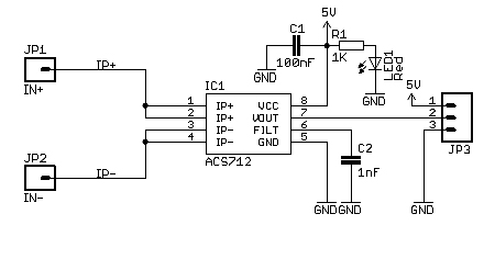
ACS712 Current Sensor Module Circuit for Microcontrollers