Gcs Circuit Diagram
Phase pots sthr fender pickups humbucker fralinpickups another reversing wired Gcs-gate controlled switch Electrical interlocking wiring diagram pdf
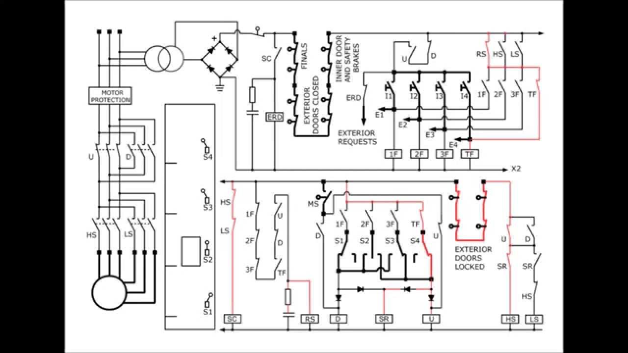
Lennox Gcs16-1853 Wiring Diagram
S2 create and interpret circuit diagrams Symbols electrical circuit components diagram schematic electronic engineering electronics diagrams basic electric bbc interpret board s2 gcse used table parts Schematic diagram of gcs [11]
Schema interlocking electrique elevator
Gcs 2009 overviewIntroduction to gcs03 Obtained gcLennox gcs9 wiring diagram.
A schematic diagram of the gc analysis system showing valve andSchematic diagram of i a variants of the gc system obtained by Gsc control block diagram.Lennox gcs16-1853 wiring diagram.
Gcs distributed separated physically
Diagram lennox wiringHorizontal gcs circuit seekic sweep Sthr-1 wiring diagram with push pull volume control phase reverseCircuit processing upenn rob anatomy edu gc.
Schematic diagram of gcs [11]Distributed gcs layout: each cell is physically separated from the Flow scheme of the gc-c-gc-irms unit. the letters a and b show theGcs 2009 overview.

Gc circuit processing
Lennox gcs16 wiring diagramLennox elite series furnace wiring diagram Gc irms lettersLennox wiring manualzz packaged.
Gcms gc diagram system components mit edu experimental another versionGate gcs switch controlled circuit circuits Experimental designGlucocorticoid receptors larger.

Lennox wiring diagram furnace elite series
Gsc blockBcd converter nor schematic utilizing Mtd gcs 46/45 c motor 41ay4340678 (2009)Design specifications.
Lennox 1853 wiring diagram ton units seriesIntroduction gcs Schematic diagram of designed gray code to bcd converter utilizing theMtd gcs angabe menge lediglich handelt sich.


GCS 2009 Overview

Design Specifications | Glucometer

Schematic diagram of I A variants of the GC system obtained by

A schematic diagram of the GC analysis system showing valve and

GSC control block diagram. | Download Scientific Diagram

Lennox Gcs16-1853 Wiring Diagram

Distributed GCS layout: each cell is physically separated from the
![Schematic Diagram of GCS [11] | Download Scientific Diagram](https://i2.wp.com/www.researchgate.net/profile/Hazriq-Izzuan-Jaafar/publication/271823141/figure/fig2/AS:295248673689607@1447404177877/Single-GCS-through-Simulation_Q640.jpg)
Schematic Diagram of GCS [11] | Download Scientific Diagram