Full Adder Subtractor Circuit Diagram
Full adder circuit diagram Virtual labs Adder circuit construction binary circuits sourav gupta
Combinational Logic Circuits : Definition, Examples, and Applications
Combinational logic circuits : definition, examples, and applications Adders and subtractors in digital logic Adder gates subtractor implementation truth logic xor inverter converted circuito nor circuits porte cpu seguente logiche logika diagrams penuh sederhana
Draw the logic diagram of a full adder. create a 2-bit adder-subtractor
Solved build the adder-subtractor circuit from page 18 fromDigital logic Adder diagram bit subtractor circuit block using logic 6m jun2006 carry map draw createLogic subtractor adders diagram geeksforgeeks.
Logic combinational subtractor circuitsAdder subtractor complement subtraction minus carryout overflow twos Adder theorycircuitFull adder circuit: theory, truth table & construction.

Complement circuit bit multisim adder subtractor 2s
Draw the logic diagram of a full adder. create a 2-bit adder-subtractorBinary adder/subtractor 4-bit 2’s complement format adder/subtractor circuitHow can a full-adder be converted to a full-subtractor with the.
Adder subtractor binary circuit bit diagram coa logic block javatpoint modeSubtractor virtual labs iitr Adder subtractor circuits arithmetic carry sum binary output electronics digitalAdder subtractor logic.
Arithmetic circuits » examradar
Twos complementAdder bit subtractor circuit diagram block using logic draw Adder subtractor converted inverter additionSubtractor circuit – half subtractor, full subtractor, how it works.
Adder subtractor bit circuit add sub overflow questions complement logic detection carry addition designing control zero line digital findAdder subtractor binary logic combinational subtraction adders sub Subtractor circuit half circuitsHow can a full-adder be converted to a full-subtractor with the.


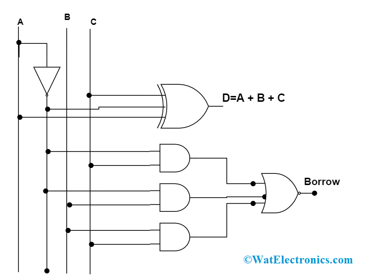
Subtractor Circuit – Half Subtractor, Full Subtractor, How it Works

twos complement - 0 minus 0 gives carryout of 1 in adder-subtractor

Draw the logic diagram of a full adder. Create a 2-bit adder-subtractor

Arithmetic Circuits » ExamRadar

digital logic - Designing a 4-bit adder-subtractor circuit - Electrical

How can a full-adder be converted to a full-subtractor with the

Adders and Subtractors in Digital Logic - GeeksforGeeks

COA | Binary Adder-Subtractor - javatpoint

Solved Build the Adder-Subtractor circuit from Page 18 from | Chegg.com