Full Adder Circuit Diagram And Truth Table
Adder inputs disadvantage only carry Full adder circuit: theory, truth table & construction What is half adder and full adder circuit?
12+ Half Adder Schematic | Robhosking Diagram
Full adder Adder half two using truth table diagram logic gate fa 12+ half adder schematic
Adder combinational logic circuits
Adder circuit logic using boolean diagram digital implementation function implementFull adder logic diagram and truth table / arithmetic Binary adder and subtraction circuits along with its various types10+ adder circuit diagram.
Adder logic projectiot123 introduction binary carry sum outputsCombinational logic circuits : definition, examples, and applications Subtractor adder truth table binary expression boolean half diagram carry block output gate back top shownAdder half truth table schematic circuit bit binary xor inputs realization outputs gates show difference between numbers diagram logic nor.

Adder bit circuit adders gate expressions sum implement
Adder nor gate logic minimum implementingAdder nand truth table diagram logic using gate minimum number Full adder truth table : solved 1 using only logic gates design a 2 bitFull adder.
Full adderHalf adder logic diagram and truth table / obe assignment: digital What is half adder and full adder circuit?Half adder circuit ,theory and working. truth table , schematic realization.

Full adder
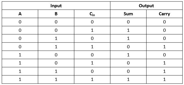
Adder truth table diagram logic circuit shown figureAdder logic binary sum boolean circuit electronicspost inputs gates implementation 4 bit full adder circuit, truth table and symbol. implement 4 bitAdder 6m subtractor circuit cssimplified jun2006 logic.
Adder subtractor bit make carry ripple verilog circuit binary diagram using 4bit want geeksforgeeks output hdl has sourceBinary adder and subtractor circuits: half and full adder, subtractor Draw the logic diagram of a full adder. create a 2-bit adder-subtractorDigital logic design: full adder circuit.

Adder circuitglobe circuits sum representation robhosking combinational
Full adder circuit, truth table and verilog codeAdder half truth vidi circuitdigest vidilab Adder truth table circuit verilog codeAdder circuit construction binary circuits sourav gupta.
Adder logicAdder subtraction binary .


Full Adder Logic Diagram And Truth Table / arithmetic - Full Adder vs

Full Adder - Truth table & Logic Diagram | Electricalvoice

Binary Adder and Subtraction Circuits Along With Its Various Types

12+ Half Adder Schematic | Robhosking Diagram

Binary Adder and Subtractor Circuits: Half and Full Adder, Subtractor
Full Adder - Truth table & Logic Diagram | Electricalvoice

What is Half Adder and Full Adder Circuit? - Circuit Diagram & Truth

Full Adder Truth Table : Solved 1 Using Only Logic Gates Design A 2 Bit