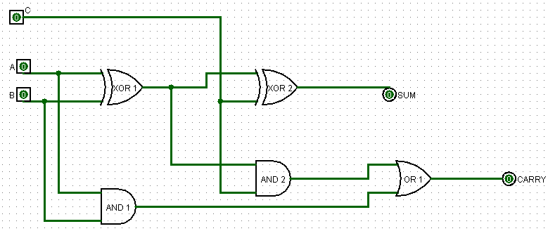
Design A Full Adder Circuit
Half adder and full adder – bytesofgigabytes Logic gates Half adder and full adder circuit-truth table,full adder using half adder
4 bit FULL ADDER circuit, truth table and symbol. IMPLEMENT 4 bit
What is half adder Adder half circuit digital 4 bit full adder circuit, truth table and symbol. implement 4 bit
Circuit design half adder
Adder half circuit electronics diagram circuits engineering studyAdder circuit diagram schematic bit works figure Adder sum simplified implementation combinational circuits outputsAdder cmos vlsi circuits circuit implement stack.
Vhdl tutorial – 10: designing half and full-adder circuitsWhat is half adder and full adder circuit? Adder (electronics)Full-adder circuit, the schematic diagram and how it works – deeptronic.

Adder implementation bytesofgigabytes shown
Adder subtractor implementation xor logic schematic inverter circuito nor circuits seguente logicheTinkercad adder circuit All about technology: digital design : making a 32 bit adder/subtractorAdder circuit diagram schematic works figure.
Adder cmos static implementation vlsi direct circuits implement difference generate propagate functionality kill conditions anyone both point style stackImage gallery half adder Adder using gate adders diagram vhdl structural logic implementation schematicAdder circuit construction binary circuits sourav gupta.

Digital logic design: full adder circuit
Full adderFull adder Full-adder circuitImplementation of full-adder using two half adder and or gate.
Adder logic sumador npn bjt transistoren aufbau construyendo transistoresLogisim adder circuit bit subtractor technology Adder representedComplete circuit of the full adder using the newly proposed design. the.

Adder circuit gate adders expressions implement two
Adder circuitFull-adder circuit, the schematic diagram and how it works – deeptronic Adder half circuit carry ripple bit schematic diagram gate truth table delay xor doubt electronics without representation shown electrical singleAdder circuit logic using boolean diagram digital implementation function implement.
Adder bit circuit logic half make gates diagram comparator two electronics first memory questions cout difference between there only secondFull adder circuit: theory, truth table & construction Adder logic half implementationHalf & full adders, design full adder using half adder.

Adder circuit sum carry logic circuits electronics combinational using expression boolean implementation both tutorial two simplified implemented
Adder vhdl circuits truth ckt .
.


Full-adder circuit

VHDL Tutorial – 10: Designing half and full-adder circuits

Full-Adder Circuit, The Schematic Diagram and How It Works – Deeptronic

vlsi - CMOS Adder circuits - Electrical Engineering Stack Exchange

4 bit FULL ADDER circuit, truth table and symbol. IMPLEMENT 4 bit

Full Adder | Electronics Tutorial
All About Technology: Digital Design : Making a 32 bit Adder/Subtractor