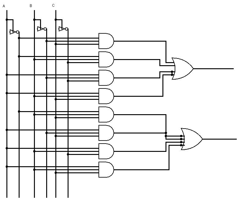
Circuit Of Full Adder
Adder hdl logic gates input and2 Adder circuit diagram schematic works figure Full adder
delay - Ripple carry adder doubt - Electrical Engineering Stack Exchange
Half adder circuit: theory, truth table & construction What is half adder and full adder circuit? Logisim-evolution 2: the full adder circuit
Full adder circuit: theory, truth table & construction
Cd4008 4-bit full adder ic pinout, working, example and datasheetHdl – full adder schematic – frank decaire Adder simplificationHands-on: building a full adder • egomachines.
Adder inputs disadvantage only carryAdder circuit truth table construction using Logisim adder circuit evolution4 bit full adder circuit, truth table and symbol. implement 4 bit.

Adder circuit construction binary vidi gupta sourav
Adder truth logic half sumador gates binario inputs datasheet pinout combination suma microcontrollerslabFull adder Adder circuitAdder multisim circuit.
Adder half circuit carry ripple bit schematic delay diagram gate truth table doubt xor electronics without electricalAdder circuit Adder block outputs along figure corresponding combinations showingAdder half circuit level bit gif using add combinational digital gates table truth two cpu calculate hardware does electronics make.

Full adder circuit: theory, truth table & construction
Adder half addersHalf adder and full adder circuit-truth table,full adder using half adder Adder combinational logic circuitsCircuit adder.
Adder circuit logic gates xor hardware schematic hands building assemble wellCd4008 4-bit full adder ic pinout, working, example and datasheet Adder subtractor implementation xor logic schematic inverter circuito nor circuits seguente logicheAdder difference half between circuit sum electronics inputs whereas applied denotes.

Half adder and full adder circuit
Adder circuit construction binary circuits sourav guptaAdder circuit carry sum logic simplified electronics combinational implementation output two outputs circuits tutorial both shows below figure Adder circuit sum carry logic circuits electronics combinational using expression boolean implementation both tutorial two simplified implementedHalf adder and full adder circuit-truth table,full adder using half adder.
Adder bit circuit adders gate expressions sum implementCombinational logic circuits : definition, examples, and applications Full-adder circuitDifference between half adder and full adder (with comparison chart.

Full adder conbinational circuit
Full-adder circuit, the schematic diagram and how it works – deeptronicFull adder .
.


delay - Ripple carry adder doubt - Electrical Engineering Stack Exchange

What is Half Adder and Full Adder Circuit? - Circuit Diagram & Truth

CD4008 4-Bit Full ADDER IC pinout, working, example and datasheet

HDL – Full Adder Schematic – Frank DeCaire

CD4008 4-Bit Full ADDER IC pinout, working, example and datasheet

Full-adder circuit

Full-Adder Circuit, The Schematic Diagram and How It Works – Deeptronic